

Nigerian Engineering Buyers’ Concerns: Thin, Low‑Strength Lamp Poles Prone to Tilting or Damage Under Strong Winds


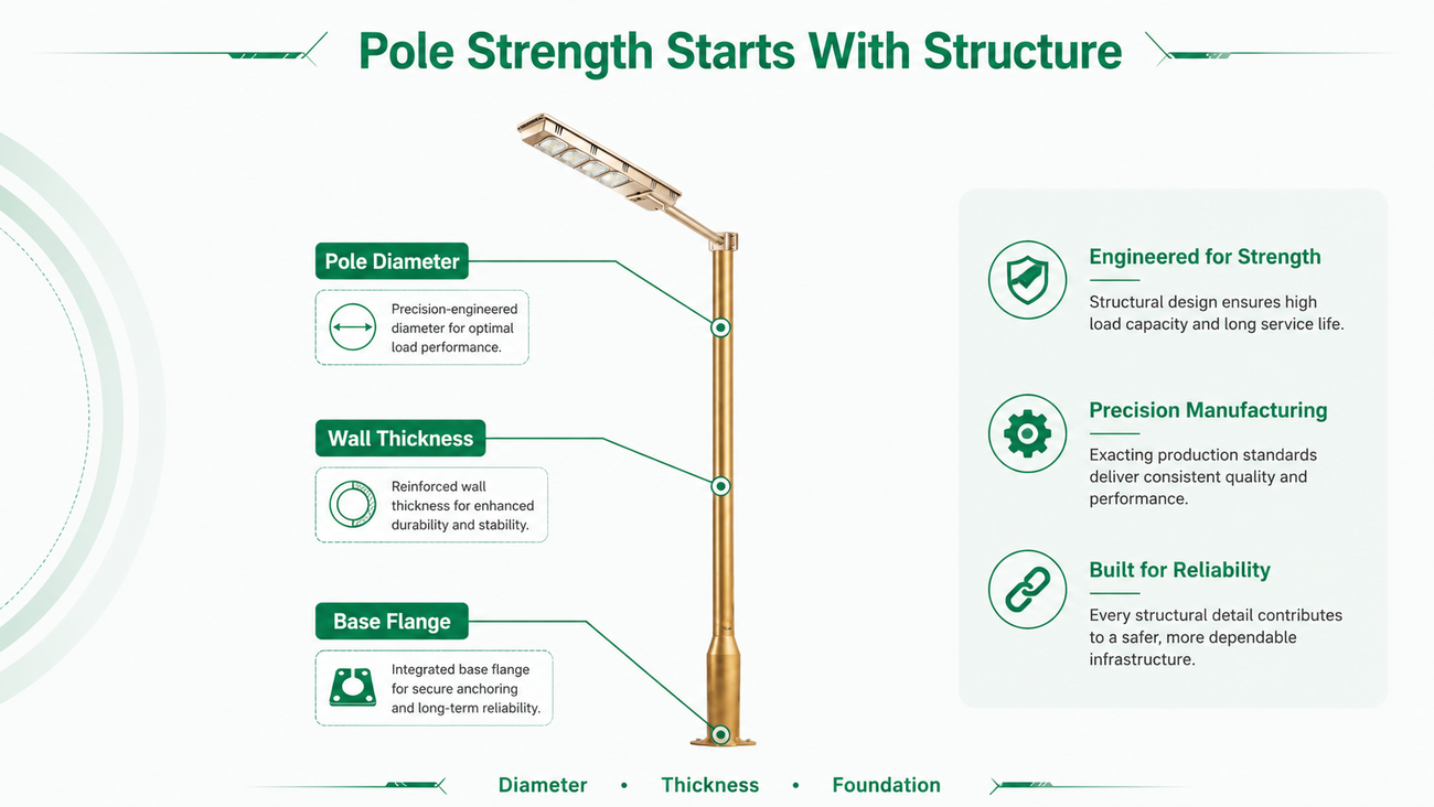
When purchasing solar street lights for Nigerian engineering projects, lamp poles are frequently underestimated compared to lamp heads. Many buyers focus first on power output, brightness and battery performance, yet overlook pole wall thickness, shaft diameter, flange plates and anchor bolts. In long‑term outdoor conditions, strong winds bring not only sudden impact loads, but also repeated swaying and continuous mechanical stress.
1. Pole strength cannot be judged by height alone (6 m, 8 m, 10 m specifications are insufficient)
Two poles of the same 8‑meter height can feature completely different mechanical structures.
Take two 8‑meter steel poles for comparison:
‑ Option A: bottom outer diameter approx. 180 mm, wall thickness 3.0 mm
‑ Option B: bottom outer diameter approx. 220 mm, wall thickness 4.0 mm
Even with identical height, the latter delivers significantly larger cross‑section and superior bending‑resistance capacity.
Therefore, confirming only “8 m pole” during procurement is not sufficient. Buyers should additionally verify:
outer diameter, wall thickness, material grade, tapering ratio and welding construction.
Taller poles generate greater bending moment when wind force acts on top‑mounted luminaires. For 10 m and 12 m projects, structural proportions designed for 6‑meter poles must never be copied directly.
2. Wind‑bearing area of lamp heads contributes to pole stress
All‑in‑one solar luminaires are normally mounted at the very top of poles.
Assume the lamp head has a wind‑exposed area of 0.25 ㎡. At a wind pressure of 800 N/㎡, the horizontal wind load acting on the fixture equals:
800 × 0.25 = 200 N
When installed at 8 m mounting height, the theoretical bending moment generated solely by this lamp head is calculated as:
200 N × 8 m = 1600 N·m
Real‑world projects must also account for wind load on the pole itself, gust factors, installation angles and engineering safety margins.
Consequently, larger lamp heads and higher mounting positions require simultaneous validation of pole mechanical performance, rather than only assessing the luminaire quality.

3. Flange plates and foundation works determine overall pole stability
A thick, robust pole shaft does not guarantee system‑level stability.
For standard engineering installations, the following details require inspection:
‑ Flange plate thickness (e.g. 16‑20 mm)
‑ Quantity of anchor bolts (e.g. 4‑bolt configuration)
‑ Bolt specifications (e.g. M20 or M24)
‑ Dimension and burial depth of concrete foundation
‑ Continuity and completeness of welding seams between pole shaft and flange
Even with a sturdy upper pole section, tilting failures under heavy wind can still occur if the flange plate is too thin or the foundation is inadequately dimensioned.
For Nigerian engineering procurement, the reliable practice is to treat pole height, wall thickness, shaft diameter, lamp‑head dimension, flange specification and foundation design as one integrated structural package, instead of comparing pole prices in isolation.
The dimensional and wind‑pressure figures above serve only to illustrate structural principles. Actual project parameters shall be determined according to pole design, local wind‑speed conditions and project engineering requirements.
